
Page 592 - Introduction to Information Optics
P. 592
10.2. A Brief Review of Types of Fiber-Optic Sensors
V4 plate with fast
axis along x
Light source
Optical
beam
Polarizer with
transmission
axis at"
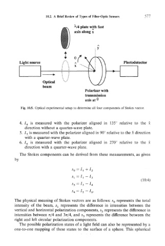
Fig. 10.5. Optical experimental setup to determine all four components of Stokes vector.
4. / 4 is measured with the polarizer aligned in 135° relative to the x
direction without a quarter-wave plate.
5. 7 5 is measured with the polarizer aligned in 90° relative to the x direction
with a quarter-wave plate.
6. I 6 is measured with the polarizer aligned in 270° relative to the x
direction with a quarter-wave plate.
The Stokes components can be derived from these measurements, as given
by
S 0 = /I + 7 2
Sj = 7 t — 1 2
(10.4)
The physical meaning of Stokes vectors are as follows: s 0 represents the total
intensity of the beam, s 1 represents the difference in intensities between the
vertical and horizontal polarization components, s 2 represents the difference in
intensities between n/4 and 3n/4, and s 3 represents the difference between the
right and left circular polarization components.
The possible polarization states of a light field can also be represented by a
one-to-one mapping of these states to the surface of a sphere. This spherical