
Page 597 - Introduction to Information Optics
P. 597
10.2. A Brief Review of Types of Fiber-Optic Sensors 581
where /, represents the input polarization vector, M n (n = 1,2,...,/) repre-
sents the nth transformation matrix, and / 0 represents the output polarization
vector.
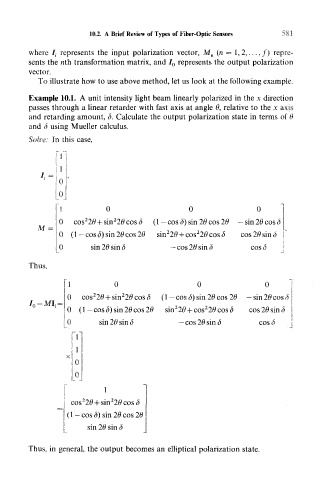
To illustrate how to use above method, let us look at the following example.
Example 10.1. A unit intensity light beam linearly polarized in the x direction
passes through a linear retarder with fast axis at angle 6, relative to the x axis
and retarding amount, 8. Calculate the output polarization state in terms of 6
and 8 using Mueller calculus.
Solve: In this case,
rr
0 0
0 co ( 1 — cos 8) sin 26 cos 26 — sin 26 cos 6
M
0 (1— cos 8) sin 26 cos 26 cos 26 sin 6
0 sin 26 sin 8 — cos 28 sin 6 cos<5
J
Thus,
0 0 0
2
2
0 cos 2$ + sin 20cos(5 (1— cos S) sin 26 cos 26 —sin 26 cos 8
2
2
0 ( 1 — cos <5) sin 26 cos 26 sm 26 + co$ 26cos8 cos 26 sin 8
0 sin 26 sin 8 —cos 26 sin 8 cos 8
°j
1
2
2
cos 2$ + sin 2# cos 8
(1 -cos 8) sin 26 cos 26
sin 26 sin 8
Thus, in general, the output becomes an elliptical polarization state.