Page 600 - Introduction to Information Optics
P. 600
584                      10. Sensing with Optics

         For the purpose of simplicity, assume that the power coupling coefficients
       of the two couplers are 0.5 with no optical loss. In this case, the output light
       intensity can be written as [13]


                                    2
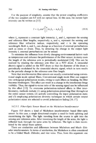
                             = / 0 cos  | --(n s L s - n rL r)       (10.8)


       where I 0 represents a constant light intensity; L s and L r represent the sensing
       and reference fiber lengths, respectively; n s and n r represent the sensing and
       reference fiber refractive indices, respectively; and A is the operating
       wavelength. Both n s and L s can change as a function of external perturbations
       such as stress or strain. Thus, by detecting the change in the output light
       intensity /, external perturbations can be sensed.
         To minimize the influence from slowly changing environmental factors such
       as temperature and enhance the performance of the fiber sensor, in many cases
       the length of the reference arm is periodically modulated [14]. This can be
       realized by winding the reference arm fiber on a PZT drum. A sinusoidal
       electric signal is added on the PZT drum so that the diameter of the drum is
       periodically modulated by the sinusoidal electric signal, which in turn results
       in the periodic change in the reference arm fiber length.
         Note that interferometric fiber sensors are usually constructed using conven-
       tional single mode optical fibers. Conventional single mode fiber can support
       two orthogonal polarization modes, owing to such effects as bending, the fiber
       becomes birefringent. This effect can result in a change in the interference fringe
       visibility. Thus, the signal-to-noise ratio of the sensing signal can be influenced
       by this effect [15]. To overcome polarization-induced effects in fiber inter-
       ferometry, methods include (1) using polarization-preserving fiber throughout
       the entire sensor system; (2) actively controlling the input polarization state;
       and (3) employing polarization diversity techniques in which certain output
       polarization states are selected to avoid polarization fading [16,17].

         10.2.3.2. Fiber-Optic Sensor Based on the Michelson Interferometer

         Figure 10.9 shows a kind of Michelson interferometer-based fiber-optic
       sensor. In this case, a single directional coupler is used for both splitting and
       recombining the light. The light traveling from the source is split into the
       sensing and reference arms. After traversing the length of the arms, the light is
       reflected back through the same arms by reflectors. The light is then recom-
       bined by the initial beam splitter.
         There are similarities and differences between Michelson and Mach-Zeh-
       nder interferometers. In terms of similarities, the Michelson is often considered
       to be a folded Mach-Zehnder, and vice versa. Thus, from this argument one

