
Page 602 - Introduction to Information Optics
P. 602
10. Sensing with Optics
Partial
reflection
mirror
Sensing
Fiber
Photodetector
/
D
LI "
Lens Mirror
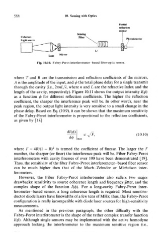
Fig. 10.10. Fabry-Perot interferometer based fiber-optic sensor.
where T and R are the transmission and reflection coefficients of the mirrors,
A is the amplitude of the input, and </> the total phase delay for a single transmit
through the cavity (i.e., 2nnL/A, where n and L are the refractive index and the
length of the cavity, respectively). Figure 10.11 shows the output intensity /(</>)
as a function <p for different reflection coefficients. The higher the reflection
coefficient, the sharper the interference peak will be. In other words, near the
peak region, the output light intensity is very sensitive to a small change in the
phase delay. Based on Eq. (10.9), it can be shown that the maximum sensitivity
of the Fabry-Perot interferometer is proportional to the reflection coefficients,
as given by [18]
oc^/F, (10.10)
del)
2
where F — 4JR/(1 — R) is termed the coefficient of finesse. The larger the F
number, the sharper (or finer) the interference peak will be. Fiber Fabry-Perot
interferometers with cavity finesses of over 100 have been demonstrated [19],
Thus, the sensitivity of the fiber Fabry-Perot interferometer-based fiber sensor
can be much higher then that of the Mach-Zehnder or Michelson inter-
ferometers.
However, the Fiber Fabry-Perot interferometer also suffers two major
drawbacks: sensitivity to source coherence length and frequency jitter, and the
complex shape of the function 7(0). For a long-cavity Fabry-Perot inter-
ferometer-based sensor, a long coherence length is required. Most semicon-
ductor diode lasers have linewidths of a few tens of MHz; thus, the Fabry-Perot
configuration is really incompatible with diode laser sources for high-sensitivity
measurements.
As mentioned in the previous paragraph, the other difficulty with the
Fabry-Perot interferometer is the shape of the rather complex transfer function
I((f>). Although single sensors may be implemented with the active homodyne
approach locking the interferometer to the maximum sensitive region (i.e..