
Page 607 - Introduction to Information Optics
P. 607
10.3. Distributed Fiber-Optic Sensors
input localised
pulse |Po perturbation(loss)
\
continuous sensing fiber
fiber end
reflection
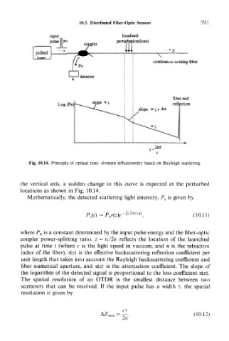
Fig. 10.14. Principle of optical time-domain reflectometry based on Rayleigh scattering.
the vertical axis, a sudden change in this curve is expected at the perturbed
locations as shown in Fig. 10.14.
Mathematically, the detected scattering light intensity, P s is given by
p s(t) = (10.11)
where P 0 is a constant determined by the input pulse energy and the fiber-optic
coupler power-splitting ratio, z = tc/2n reflects the location of the launched
pulse at time t (where c is the light speed in vacuum, and n is the refractive
index of the fiber), r(z) is the effective backscattering reflection coefficient per
unit length that takes into account the Rayleigh backscattering coefficient and
fiber numerical aperture, and a(z) is the attenuation coefficient. The slope of
the logarithm of the detected signal is proportional to the loss coefficient a(z).
The spatial resolution of an OTDR is the smallest distance between two
scatterers that can be resolved. If the input pulse has a width T, the spatial
resolution is given by
C"C
(10.12)
2n