
Page 609 - Introduction to Information Optics
P. 609
10.3. Distributed Fiber-Optic Sensors 593
sensors coils
Tl T2 T3
OOP
output T(z)
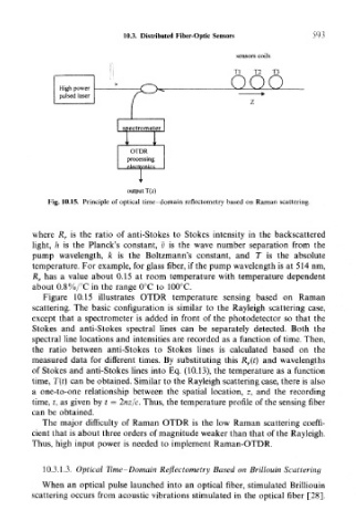
Fig. 10.15. Principle of optical time -domain reflectometry based on Raman scattering.
where R r is the ratio of anti-Stokes to Stokes intensity in the backscattered
light, h is the Planck's constant, v is the wave number separation from the
pump wavelength, k is the Boltzmann's constant, and T is the absolute
temperature. For example, for glass fiber, if the pump wavelength is at 514 nm,
R r has a value about 0.15 at room temperature with temperature dependent
about 0.8%/°C in the range 0°C to 100°C.
Figure 10.15 illustrates OTDR temperature sensing based on Raman
scattering. The basic configuration is similar to the Rayleigh scattering case,
except that a spectrometer is added in front of the photodetector so that the
Stokes and anti-Stokes spectral lines can be separately detected. Both the
spectral line locations and intensities are recorded as a function of time. Then,
the ratio between anti-Stokes to Stokes lines is calculated based on the
measured data for different times. By substituting this R r(t) and wavelengths
of Stokes and anti-Stokes lines into Eq. (10.13), the temperature as a function
time, T(t) can be obtained. Similar to the Rayleigh scattering case, there is also
a one-to-one relationship between the spatial location, z, and the recording
time, t, as given by t = 2nz/c. Thus, the temperature profile of the sensing fiber
can be obtained.
The major difficulty of Raman OTDR is the low Raman scattering coeffi-
cient that is about three orders of magnitude weaker than that of the Rayleigh.
Thus, high input power is needed to implement Raman-OTDR.
10.3.1.3. Optical Time-Domain Reflectometry Based on Brillouin Scattering
When an optical pulse launched into an optical fiber, stimulated Brilliouin
scattering occurs from acoustic vibrations stimulated in the optical fiber [28],