
Page 669 - Introduction to Information Optics
P. 669
! 1.4. Information Display Using Electro-Optic Spatial Light Modulators 653
coated with a thin electrically conductive but optically transparent metallic
film (such as indium-tin-oxide, ITO) called the alignment layer; then the layer
is rubbed with a fine cotton cloth in a unidirectional manner. Fine grooves
about several nanometers wide are formed by rubbing and thus cause the
liquid crystal molecules to lie parallel to the grooves. This rubbing method has
been widely used for fabricating large-panel LC devices. High-quality align-
ment can be made by vacuum deposition of a fine silicon monoxide (SiO) layer
to create microgroves onto the surface of the glass for aligning LC molecules.
If each alignment layer is polished with different directions, the molecular
orientation rotates helically about an axis normal to plates, such as the
situation shown in Fig. 11.29. The configuration shown in Fig. 11.29 is called
the twist alignment as the back glass plate is twisted at an angle with respect
to the front plate. Hence, if the alignment directions between the two plates are
90°, we have the perpendicular alignment. If the alignment directions are
parallel, the LC molecules are parallelly aligned, and we have parallel align-
ment [39].
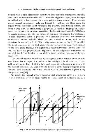
The twisted nematic liquid can act as a polarization rotator under certain
conditions. For example, if a x-plane polarized light is incident on the crystal
cell, as shown in Fig. 11.30, the light will rotate its polarization in step with
the twisted structure (i.e., align with the directors as the light propagates along
the cell) and eventually will leave the cell with its polarization aligned along
the v-direction [40].
We model the twisted nematic liquid crystal, which has width d, as a stack
of N incremental layers of equal widths Az = d/N. Each of the layers acts as a
Alignment
direction
/AliAlignment
direction
E
Fig. 11.30. Twisted nematic liquid crystal as a polarization rotator.