
Page 665 - Introduction to Information Optics
P. 665
11,4. Information Display Using Electro-Optic Spatial Light Modulators 649
BS1
Blocker
X
M2
BE2 L BS2 Scanning Mirrors
Recording stage
Reconstruction stage
Eiectro-node mesh Deflecting coils Electron gun
laser
Output Sight
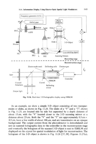
Fig. 11.24. Real-time 3-D holographic display using EBSLM.
As an example, we show a simple 3-D object consisting of two transpar-
encies or slides, as shown in Fig. 11.24. The slides of a "V" and a "T", shown
in Fig. 11.25, are located side by side but separated by a depth distance of
about 15 cm, with the "V" located closer to the 2-D scanning mirror at a
distance about 23 cm. Both the "V" and the "T" are approximately 0.5 cm x
0.5 cm, have a line width of about 100 jum, and are transmissive on an opaque
background. The output current from the photodetector is demodulated and
sent as scanned holographic data to the controller in the reconstruction stage
and eventually the hologram of the scanned 3-D object is sent to EBSLM and
displayed on the crystal for spatial modulation of light for reconstruction. The
hologram of the 3-D object is shown in Fig. 11.26 [37,38]. Figures 11.27(a),