
Page 664 - Introduction to Information Optics
P. 664
648 11. Information Display with Optics
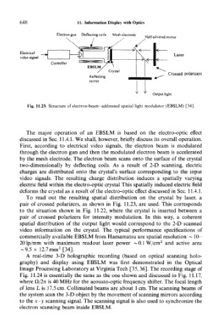
Electron gun Deflecting coils Mesh electrode „ ,, .. , .
, , , Half-silvered mirror
Electrical
video signal
Output light
Fig. 11.23. Structure of electron-beam-addressed spatial light modulator (EBSLM) [34].
The major operation of an EBSLM is based on the electro-optic effect
discussed in Sec. 11.4.1. We shall, however, briefly discuss its overall operation.
First, according to electrical video signals, the electron beam is modulated
through the electron gun and then the modulated electron beam is accelerated
by the mesh electrode. The electron beam scans onto the surface of the crystal
two-dimensionally by deflecting coils. As a result of 2-D scanning, electric
charges are distributed onto the crystal's surface corresponding to the input
video signals. The resulting charge distribution induces a spatially varying
electric field within the electro-optic crystal This spatially induced electric field
deforms the crystal as a result of the electro-optic effect discussed in Sec. 11.4.1.
To read out the resulting spatial distribution on the crystal by laser, a
pair of crossed polarizers, as shown in Fig. 11.23, are used. This corresponds
to the situation shown in Fig. 11.22, where the crystal is inserted between a
pair of crossed polarizers for intensity modulation. In this way, a coherent
spatial distribution of the output light would correspond to the 2-D scanned
video information on the crystal. The typical performance specifications of
commercially available EBSLM from Hamamatsu are spatial resolution ~ 10-
2
201p/mm with maximum readout laser power ~0.1 W/cm and active area
2
-9.5 x 12.7mm [34].
A real-time 3-D holographic recording (based on optical scanning holo-
graphy) and display using EBSLM was first demonstrated in the Optical
Image Processing Laboratory at Virginia Tech [35,36]. The recording stage of
Fig. 11.24 is essentially the same as the one shown and discussed in Fig. 11.17,
where Q/2n is 40 MHz for the acousto-optic frequency shifter. The focal length
of lens L is 17.5 cm. Collimated beams are about 1 cm. The scanning beams of
the system scan the 3-D object by the movement of scanning mirrors according
to the x-y scanning signal. The scanning signal is also used to synchronize the
electron scanning beam inside EBSLM.