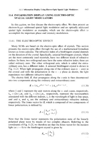
Page 659 - Introduction to Information Optics
P. 659
11.4. Information Display Using Electro-Optic Spatial Light Modulators  643

       11.4. INFORMATION DISPLAY USING ELECTRO-OPTIC
            SPATIAL LIGHT MODULATORS

          In this section, we first discuss the electro-optic effect. We then present an
       electron-beam-addressed spatial light modulator and an optically addressed
       spatial light modulator as examples, which use the electro-optic effect to
       accomplish the important phase and intensity modulation.


       11.4.1. THE ELECTRO-OPTIC EFFECT
          Many SLMs are based on the electro-optic effect of crystals. This section
       presents the electro-optic effect through the use of a mathematical formalism
       known as Jones calculus. The refractive index of a birefringent crystal depends
       on the direction of the crystal. Specifically, uniaxial birefringent crystals, which
       are the most commonly used materials, have two different kinds of refractive
       indices. In them, two orthogonal axes have the same refractive index; these are
       called ordinary axes. The other orthogonal axis, which is called the extra-
       ordinary axis, has a different index. A uniaxial birefringent crystal is shown in
       Fig. 11.21. When light propagates along one of the ordinary axes (z — axis) in
       the crystal and with the polarization in the x — y plane as shown, the light
       experiences two different refractive indices.
          The electric field, E, that propagates along the z-axis is then decomposed
       into two components along the ordinary and extraordinary axes:
                                  w    k z}     /(w
                         E = xA nti ^ °' ~ -°  + yA na e '<>' ~ *--'> ,  (11.30)

       where x and y represent the unit vectors along the x- and y-axes, respectively,
       k no = (2n//. v)n 0 and k ne — (27t/A,.)n e, respectively, represent the wavenumbers
       associated with the different indexes, A v is the wavelength of light in free space,
       and and n 0 and n e are the ordinary and extraordinary refractive indexes,
       respectively. The Jones vector for £", which is composed of two components of
       linear polarization, is defined by:


       Note that the Jones vector represents the polarization state of the linearly
       polarized plane wave by means of two complex phasors. Referring to the
       coordinates of Fig. 1 1.21, we therefore see that the Jones vector for the incident
       light (at z — 0) to the birefringent crystal is given by

