
Page 658 - Introduction to Information Optics
P. 658
642 11. Information Display with Optics
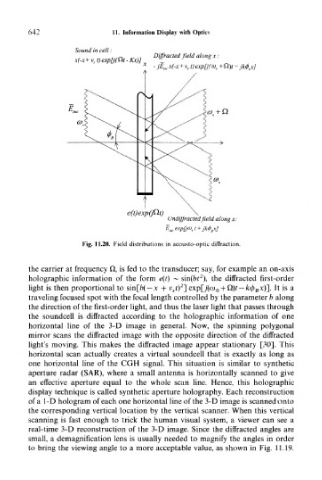
Sound in cell :
Diffracted field along x :
s(-x + v s t
- jk<f> tx]
e(t)exp(pt)
Undiffracted field along x:
Fig. 11.20. Field distributions in acousto-optic diffraction.
the carrier at frequency Q, is fed to the transducer; say, for example an on-axis
2
holographic information of the form e(t) ~ sin(frt ), the diffracted first-order
2
light is then proportional to sin[/)( — x + v st) ] exp[j(co 0 + U)t —/c<^ Bx)]. It is a
traveling focused spot with the focal length controlled by the parameter b along
the direction of the first-order light, and thus the laser light that passes through
the soundcell is diffracted according to the holographic information of one
horizontal line of the 3-D image in general. Now, the spinning polygonal
mirror scans the diffracted image with the opposite direction of the diffracted
light's moving. This makes the diffracted image appear stationary [30]. This
horizontal scan actually creates a virtual soundcell that is exactly as long as
one horizontal line of the CGH signal. This situation is similar to synthetic
aperture radar (SAR), where a small antenna is horizontally scanned to give
an effective aperture equal to the whole scan line. Hence, this holographic
display technique is called synthetic aperture holography. Each reconstruction
of a 1-D hologram of each one horizontal line of the 3-D image is scanned onto
the corresponding vertical location by the vertical scanner. When this vertical
scanning is fast enough to trick the human visual system, a viewer can see a
real-time 3-D reconstruction of the 3-D image. Since the diffracted angles are
small, a demagnification lens is usually needed to magnify the angles in order
to bring the viewing angle to a more acceptable value, as shown in Fig. 11.19.