
Page 657 - Introduction to Information Optics
P. 657
11.3. 3-D Holographic Display 641
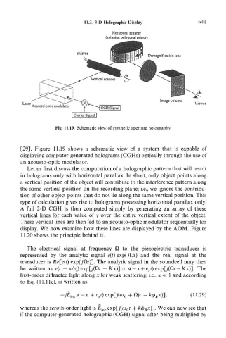
Horizontal scanner
(spinning polygonal mirror)
Demagnification lens
. . 7VT VV*^ Viewer
Laser 4
Acousto-optic modulator •
[Carrier Signal!
Fig. 11.19. Schematic view of synthetic aperture holography.
[29]. Figure 11.19 shows a schematic view of a system that is capable of
displaying computer-generated holograms (CGHs) optically through the use of
an acousto-optic modulator.
Let us first discuss the computation of a holographic pattern that will result
in holograms only with horizontal parallax. In short, only object points along
a vertical position of the object will contribute to the interference pattern along
the same vertical position on the recording plane; i.e., we ignore the contribu-
tion of other object points that do not lie along the same vertical position. This
type of calculation gives rise to holograms possessing horizontal parallax only.
A full 2-D CGH is then computed simply by generating an array of these
vertical lines for each value of y over the entire vertical extent of the object.
These vertical lines are then fed to an acousto-optic modulator sequentially for
display. We now examine how these lines are displayed by the AOM. Figure
11.20 shows the principle behind it.
The electrical signal at frequency Q to the piezoelectric transducer is
represented by the analytic signal e(t) exp(jOt) and the real signal at the
transducer is Re{e(t] exp(jQt)3- The analytic signal in the soundcell may then
be written as e(t — x/v s) exp[j(Q.t — Kx)] oc s( — x + v st) exp[j(Qr — KxJ], The
first-order diffracted light along x for weak scattering; i.e., a « 1 and according
to Eq. (11.lie), is written as
-jE, ncs(~x + v st) exp[j(ft> 0 + 0)r - k(f> Bx)~], (11.29)
whereas the zeroth-order light is E incexp[j(a) 0t + k$ Bx)~], We can now see that
if the computer-generated holographic (CGH) signal after being multiplied by