
Page 653 - Introduction to Information Optics
P. 653
11.3. 3-D Holographic Display 637
reconstruction hologmm of toe-point
plane wave object
*
*
virtual real
usage image
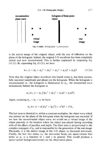
Fig. 11.16(b). Holographic reconstruction.
is the mirror image of the original object, with the axis of reflection on the
plane of the hologram. Indeed, the original 3-D wavefront has been completely
stored and now reconstructed. This is further explained by inspecting Eq.
(11.21). By expanding Eq. (11.21), we have
t(x, y) = (11.24)
Note that the original object wavefront (the fourth term) \l/ 0 has been success-
fully recorded (amplitude and phase) on the hologram. When the hologram is
reconstructed; i.e., the hologram is illuminated by i^ rc, the transmitted wave
immediately behind the hologram is
2
<Mx, y) = «A rc[ W +
Again, assuming \l/ rc = \j/ r = a, we have
2
MX, y) = a[|^| + |
The last term is identical to, within a constant multiplier, the object wave which
was present on the plane of the hologram when the hologram was recorded. If
we view the reconstructed object wave, we would see a virtual image of the
object precisely at the location where the object was placed during recording
with all the effects of parallax and depth. The third term is proportional to the
complex conjugate of \l/ 0 and is responsible for the generation of the real image.
Physically, it is the mirror image of the 3-D object, as discussed previously.
Finally, the first two terms; i.e., the zero-order beam, are space-variant bias
terms as \l/ 0 is a function of x and y in general. This would produce a
space-variant background (noise) on the observation plane.