Page 237 - Introduction to Marine Engineering
P. 237

216  Stee ring gear

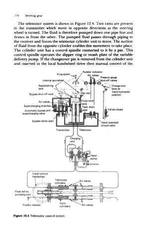
                   The  telemotor  system  is shown  in Figure  12.4. Two rams are  present
                 in  the  transmitter  which  move  in  opposite  directions  as  the  steering
                 wheel is turned. The  fluid  is therefore  pumped down one  pipe line and
                 drawn  in  from  the  other.  The  pumped  fluid  passes through  piping to
                 the receiver and forces the telemotor  cylinder unit to move. The suction
                 of fluid from  the opposite  cylinder enables this movement to take place.
                 The  cylinder unit has a control  spindle  connected  to  it by a  pin.  This
                 control  spindle operates the  slipper ring or  swash plate of the  variable
                 delivery pump. If the changeover  pin is removed  from the cylinder unit
                 and  inserted  in  the  local  handwheel  drive  then  manual control  of  the


                                                     Rudder  indicator
                                        King-spoke  _ i
                                                        Air valves
                                                               Pressure  gauge
                                I nternal spu rwheei _  -" " ' ^  shut-off valves
                                                "
                              Replenishing                           Change-over
                              tank                                   lever at
                                                                     'hand-hydraulic'
                         By pass shut-off code                       position
                              Air valves
                      Supercharging  chamber
                                                                   Valves closed.
                      Automatic bypass and
                     supercharging valve
                          Bypass valves open


                 Pipes led to
                 pumping unit

                                         Gyro
                     Duplex receiver                 Air valves
                                         cylinders
                 Figure  12.4 Telemotor control  system
   232   233   234   235   236   237   238   239   240   241   242