
Page 234 - Introduction to Marine Engineering
P. 234
214 Steering gear
Circular
•floating Floating
ring ring
Central
valve
arrangement
(b)
(a)
Gudgeon pin
and dipper
fitted in Floating
floating ring ring
Cylinder
body
rotation
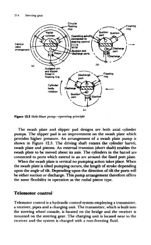
Figure 12.2 Hele-Shaw pump—operating principle
The swash plate and slipper pad designs are both axial cylinder
pumps. The slipper pad is an improvement on the swash plate which
provides higher pressure. An arrangement of a swash plate pump is
shown in Figure 12.3. The driving shaft rotates the cylinder barrel,
swash plate and pistons. An external trunnion (short shaft) enables the
swash plate to be moved about its axis. The cylinders in the barrel are
connected to ports which extend in an arc around the fixed pott plate.
When the swash plate is vertical no pumping action takes place. When
the swash plate is tilted pumping occurs, the length of stroke depending
upon the angle of tilt. Depending upon the direction of tilt the ports will
be either suction or discharge. This pump arrangement therefore offers
the same flexibility in operation as the radial piston type.
Telemotor control
Telemotor control is a hydraulic control system employing a transmitter,
a receiver, pipes and a charging unit. The transmitter, which is built into
the steering wheel console, is located on the bridge and the receiver is
mounted on the steering gear. The charging unit is located near to the
receiver and the system is charged with a non-freezing fluid.