
Page 238 - Introduction to Marine Engineering
P. 238
Steering gear 21"
steering gear is possible. Stops are fitted on the receiver to limit
movement to the maximum rudder angle required. The charging unit
consists of a tank, a pump, and shut-off cocks for each and is fitted in the
main piping between the transmitter and receiver.
In the transmitter a replenishing tank surrounds the rams, ensuring
that air cannot enter the system. A bypass between the two cylinders
opens as the wheel passes midships. Also at mid position the
supercharging unit provides a pressure in the system which ensures
rapid response of the system to a movement of the wheel. This
supercharging unit also draws in replenishing fluid if required in the
system, and provides a relief valve arrangement if the pressure is too
high. Pressure gauges are connected to each main pipeline and air vent
cocks are also provided.
In normal operation the working pressure of about 20 to 30 bar, or
the manufacturer's given figure, should not be exceeded. The wheel
should not be forced beyond the 'hard over' position as this will strain
the gear. The replenishing tank should be checked regularly and any
lubrication points should receive attention. Any leaking or damaged
equipment must be repaired or replaced as soon as possible. The system
should be regularly checked for pressure tightness. The rudder
response to wheel movement should be checked and if sluggish or slow
then air venting undertaken. If, after long service, air venting does not
remove sluggishness, it may be necessary to recharge the system with
new fluid.
Wheel
To pump
control rod
Mains
supply
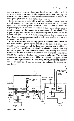
Figure 12.5(a) Control box