
Page 269 - Introduction to Marine Engineering
P. 269
244 Fire fighting and safety
cylinders of gas to be released into the space and this is done by a hand
operated lever.
The machinery space system is designed to quickly discharge the
complete battery of cylinders. Before the gas is released the space must
be clear of personnel and sealed against entry or exhausting of air.
The discharge valve is located in a locked cabinet, with the key in a
glass case nearby. Opening the cabinet sounds an alarm to warn
personnel of the imminent discharge of the gas. The discharge valve is
opened and an operating lever pulled.
The operating lever opens two gas bottles which pressurise a gang
release cylinder that, in turn, moves an operating cable to open all the
bottles in the battery. The carbon dioxide gas then quickly floods the
machinery space, filling it to 30% of its volume in two minutes or Jess.
The air sampling system can be checked when the holds are empty by
using a smoking rag beneath a sampling point. Flow indicators, usually
small propellers, are fitted at the outlet points of the smoke detecting
pipes as a visual check and an assurance that the pipes are clear. To
check for leakage the gas cylinders can be weighed or have their liquid
levels measured by a special unit.
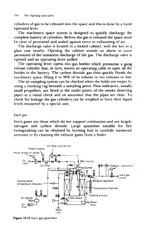
Inert gas
Inert gases are those which do not support combustion and are largely
nitrogen and carbon dioxide. Large quantities suitable for fire
extinguishing can be obtained by burning fuel in carefully measured
amounts or by cleaning the exhaust gases from a boiler.
Oil filter-pilot burner
Pressure gauge
Motor driven oil pump
Pressure controllers
Inert gas
outlet
Cooling water Moisture separator
temperature indicator
Combustion chamber
Cooling annulus
Water
drain
Figure 13.13 Inert gas generator