
Page 190 - Introduction to Microcontrollers Architecture, Programming, and Interfacing of The Motorola 68HC12
P. 190
6.4 Calling And Returning Mechanisms 167
layout of the subroutine is shown in Figure 6.37. If one wants to call subroutine SUB at
its ith entry point, i = 0 to initialize it, i = 1 to output to it, and i = 2 to terminate its
use, then, assuming that the value of i is in accumulator B, the calling sequence in
Figure 6.38 can be used.
Notice that the machine code for the calling sequence stays the same regardless of
internal changes to subroutine SUB. That is, if SUB1 were to increase in size due to
modifications of the code, the calling program in Figure 6.38 is not changed at all. This
technique limits the interaction between program segments so that changes in one
segment do not propagate to other segments. So if a bug is fixed in the subroutine and
the calling routine is in a different ROM or a different part of EEPROM, it won't have
SUB: DC.W SUBO
DC.W SUB1
DC.W SUB2
Figure 639. A Jump Vector
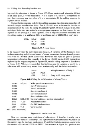
to be changed when the subroutine size changes. A variation of this technique uses
indirect addressing and addresses instead of LBRA instructions, because fewer bytes are
used with DC .Ws than LBRA instructions. However, this does not yield a position
independent subroutine. For example, if the layout of SUB has the LBRA instructions
replaced by the program segment in Figure 6.39, then its calling sequence is that shown
in Figure 6.40. Although we described this technique and its variation as useful for a
subroutine with several entry points, either works equally well for distinct subroutines.
ASLD ; Multiply contents of D by 2
LDX #SUB
JSR [ D, X ] ; Jump to ith entry point
Figure 6.40. Calling the ith Subroutine of a Jump Vector
LEAS -2,SP ; Make space for return address
PSHY ; Save Y above return
PSHX ; Save X above that
PSHA ; Save accumulator A
PSHB ; Save accumulator B
PSHC ; Save condition codes
LEAX RET, PCR ; Get return address ( position independent)
STX 7 , SP ; Place return address
LDX $ FFF6 ; Get SWI handler address
JMP 0, X ; Go to handler
RET: (next instruction)
Figure 6.41. Emulation of SWI
Now we consider some variations of subroutines. A handler is really just a
subroutine that "handles" an interrupt. The software interrupt instruction SWI pushes all
the registers onto the hardware stack, except SP, and then loads the program counter with
the contents of locations $FFF6 and $FFF7. The sequence in Figure 6.41 produces the