
Page 191 - Introduction to Microcontrollers Architecture, Programming, and Interfacing of The Motorola 68HC12
P. 191
168 Chapter 6 Assembly Language Subroutines
same effect as the SWI instruction except for minor changes in the CC and X registers.
The subroutine at the address contained in $FFF6 and $FFF7 is called the SWI handler,
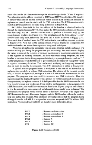
A handler must end in an RTI instruction rather than an RTS instruction because all
registers are pushed onto the stack with the SWI instruction. The RTI instruction at the
end of an SWI handler does the same thing as the code in Figure 6.42.
SWI differs from BSR in that the address of the handler is obtained indirectly
through the implied address $FFF6. This makes the SWI instruction shorter, in this case
one byte long. An SWI handler can be made to perform a function, such as our
ubiquitous dot product. See Figure 6.43. The initialization of the high-address "vector"
need be done only once, before the first SWI call is made, as shown in Figure 6.44a.
Then, each time it's called, insert the SWI instruction in your calling program, as shown
in Figure 6.44b. Note that in the calling routine, we pass arguments in registers; but
inside the handler, we access these arguments using stack techniques.
When you are debugging a program, you can use a program called a debugger or a
monitor to help you debug the program that you are writing. You may want to display
the values in some of the registers or memory locations or to insert some data into some
of the registers or memory locations. As used with most debug programs, the SWI
handler is a routine in the debug program that displays a prompt character, such as "*,"
on the terminal and waits for the user to give commands to display or change the values
in registers or memory locations. This can be used to display or change any amount of
data or even to modify the program. This SWI instruction is called a breakpoint.
A typical monitor program inserts a breakpoint at the start of an instruction by
replacing the opcode byte with an SWI instruction. The address of the replaced opcode
byte, as well as the byte itself, are kept in a part of RAM that the monitor uses for this
purpose. The program now runs until it encounters the SWI breakpoint. Then the
registers might be displayed together with a prompt for further commands to examine or
change memory or register contents. It is indispensable that the SWI instruction be one
byte long to be used as a breakpoint. If you tried to put breakpoints in the program with
a JSR instruction, you would have to remove three bytes. If your program had a branch
in it to the second byte being removed, unfathomable things might begin to happen! The
problem in your program would be even harder to find now. However, if the single-word
SWI instruction is used, this cannot happen, and the SWI handler call can be made to
help you debug the program. One limitation of breakpoints is that the program being
debugged must be in RAM. It is not possible to replace an opcode in ROM with an SWI
instruction. Programs already in ROM are therefore more difficult to debug.
PULC ; Restore condition codes
PULB ; Restore accumulator B
PULA ; Restore accumulator A
PULX ; Restore X
PULY ; Restore Y
RTS ; Restore PC
Figure 6.42. Emulation of RTI