
Page 61 - Introduction to Microcontrollers Architecture, Programming, and Interfacing of The Motorola 68HC12
P. 61
38 Chapter 2 The Instruction Set
2.3 Logic Instructions
Logic instructions (see Table 2.6) are used to set and clear individual bits in A, B, and
CCR. They are used by compilers, programs that translate high-level languages to
machine code, to manipulate bits to generate machine code. They are used by controllers
of machinery because bits are used to turn things on and off. They are used by operating
systems to control input-output (I/O) devices and to control the allocation of time and
memory on a computer. Logic instructions are missing in calculators. That makes it hard
to write compilers and operating systems for calculators, no matter how much memory
they have. Returning to a problem at the end of Chapter 1, we now say a programmable
calculator is not a von Neumann computer because it does not have logic instructions or
any efficient replacements for these instructions with combinations of other instructions.
(This differentiation may be pedagogically satisfying, but unfortunately, von Neumann's
original computer is not a von Neumann computer by this definition. Because we are
engineers and not historians, we say that programmable calculators, and von Neumann's
original computer, are not von Neumann computers in the strictest sense because they
cannot support compilers and operating systems efficiently.)
Consider now the logic instructions that make a computer a computer and not a
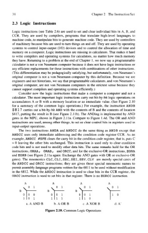
calculator. The most important logic instructions carry out bit-by-bit logic operations on
accumulators A or B with a memory location or an immediate value. (See Figure 2.10
for a summary of the common logic operations.) For example, the instruction ANDB
$ 817 carries out a bit-by-bit AND with the contents of B and the contents of location
$817, putting the result in B (see Figure 2.lib). The ANDing is implemented by AND
gates in the MPU, shown in Figure 2.1 la. Compare to Figure 1.4d. The OR and AND
instructions are used, among other things, to set or clear control bits in registers used in
input-output operations.
The two instructions ANDA and ANDCC do the same thing as ANDB except that
ANDCC uses only immediate addressing and the condition code register CCR. As an
example, ANDCC #$FE clears the carry bit in the condition code register, that is, puts C
= 0 leaving the other bits unchanged. This instruction is used only to clear condition
code bits and is not used to modify other data bits. The same remarks hold for the OR
instructions, ORAA, GRAB, and ORCC, and for the exclusive-OR instructions, EORA
and EORB (see Figure 2.1 la again: Exchange the AND gates with OR or exclusive-OR
gates). The mnemonics CLC, CLI, SEC, SEI, SEV, CLV are merely special cases of
the ANDCC and ORCC instructions; they are given these special mnemonic names to
permit assembly-language programs written for the 6811 to be used without modification
in the 6812. While the ANDCC instruction is used to clear bits in the CCR register, the
ORCC instruction is used to set bits in that register. There is no EORCC instruction.
Figure 2.10. Common Logic Operations