
Page 145 - Introduction to Mineral Exploration
P. 145
128 J. MILSOM
nT require physical contact with the ground and
Total field can therefore be made from aircraft. Inevitably,
(a) direction
100 there is some loss of sensitivity, since detectors
are further from sources, but this may even
be useful in filtering out local effects from
manmade objects. The main virtue of airborne
work is, however, the speed with which large
Magnetic areas can be covered. Surveys may be flown
either at a constant altitude or (more com-
monly in mineral exploration) at a (nominally)
g.u.
constant height above the ground. Aircraft
(b) 10 are often fitted with multiple sensors and
most installations include a magnetometer
(Fig. 7.2).
5
Airborne surveys require good navigational
control, both at the time of survey and later,
when flight paths have to be plotted (recov-
Gravity ered). Traditionally, the pilot was guided by a
% navigator equipped with maps or photo-mosaics
(c) 5 showing the planned line locations. Course
changes were avoided unless absolutely neces-
sary and in many cases the navigator’s main job
Electromagnetic was to ensure that each line was at least begun
−5 (CWEM) in the right place. Although infills were (and
are) required if lines diverged too much, a line
that was slightly out of position was preferred
to one that continually changed direction and
% was therefore difficult to plot accurately.
Low level navigation is not easy, since even
(d) 5 the best landmarks may be visible for only a
few seconds when flying a few hundred meters
above the ground, and navigators’ opinions of
Electromagnetic where they had been would have been very in-
(VLF)
adequate bases for geophysical maps. Tracking
−5
cameras were therefore used to record images,
either continuously or as overlapping frames,
on 35 mm film. Because of the generally small
terrain clearance, very wide-angle (“fish-eye”)
lenses were used to give broad, although dis-
torted, fields of view. Recovery was done dir-
ectly from the negatives and even the most
experienced plotters were likely to misidentify
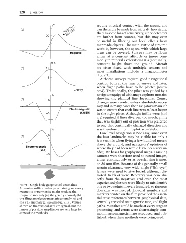
FIG. 7.1 Single body geophysical anomalies. one or two points in every hundred, so rigorous
A massive sulfide orebody containing accessory
magnetite or pyrrhotite might produce the checking was needed. Fiducial numbers and
magnetic anomaly (a), the gravity anomaly (b), markers printed on the film provided the essen-
the Slingram electromagnetic anomaly (c), and tial cross-references between geophysical data,
the VLF anomaly (d; see also Fig. 7.15). Values generally recorded on magnetic tape, and flight
shown on the vertical axes are typical, but the paths. Mistakes could be made at every stage in
ranges of possible amplitudes are very large for processing, and errors were distressingly com-
some of the methods. mon in aeromagnetic maps produced, and pub-
lished, when these methods were being used.