
Page 150 - Introduction to Naval Architecture
P. 150
136 STRENGTH
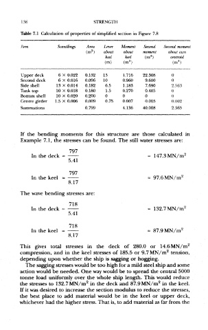
Table 7.1 Calculation of properties of simplified section in Figure 7.8
Item Scantlings Area Lever Moment Second Second moment
2
(m ) about about moment about own
4
keel keel (m ) centroid
4
3
(m) (m ) (m )
Upper deck 6 X 0.022 0.132 13 1.716 22.308 0
Second deck 6 X 0.016 0.096 10 0.960 9.600 0
Side shell 13 X 0.014 0.182 6.5 1.183 7.690 2.563
Tank top 10 X 0.018 0.180 1.5 0.270 0.405 0
Bottom shell 10 X 0.020 0.200 0 0 0 0
Centre girder 1.5 X 0.006 0.009 0.75 0.007 0.005 0.002
Summations 0.799 4.136 40.008 2.565
If the bending moments for this structure are those calculated in
Example 7.1, the stresses can be found. The still water stresses are:
In the deck
In the keel
The wave bending stresses are:
In the deck
In the keel
2
This gives total stresses in the deck of 280.0 or 14.6MN/m
2
compression, and in the keel stresses of 185.5 or 9.7MN/m tension,
depending upon whether the ship is sagging or hogging.
The sagging stresses would be too high for a mild steel ship and some
action would be needed. One way would be to spread the central 5000
tonne load uniformly over the whole ship length. This would reduce
2
2
the stresses to 132.7MN/m in the deck and 87.9 MN/m in the keel.
If it was desired to increase the section modulus to reduce the stresses,
the best place to add material would be in the keel or upper deck,
whichever had the higher stress. That is, to add material as far from the