
Page 162 - Introduction to Naval Architecture
P. 162
y = distance of centroid of A from the NA
7 = second moment of complete section about the
NA
t = thickness of section at y
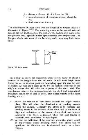
The distribution of shear stress over the depth of an I-beam section is
illustrated in Figure 7.12. The stress is greatest at the neutral axis and
zero at the top and bottom of the section. The vertical web takes by far
the greatest load, typically in this type of section over 90 per cent. The
flanges, which take most of the bending load, carry very little shear
stress.
Figure 7.12 Shear stress
In a ship in waves the maximum shear forces occur at about a
quarter of the length from the two ends. In still water large shear
forces can occur at other positions depending upon the way the ship
is loaded. As with the I-beam it will be the vertical elements of the
ship's structure that will take the majority of the shear load. The
distribution between the various elements, the shell and longitudinal
bulkheads say, is not so easy to assess. The overall effects of the shear
loading are to:
(1) distort the sections so that plane sections no longer remain
plane. This will affect the distribution of bending stresses
across the section. Generally the effect is to increase the
bending stress at the corners of the deck and at the turn of
bilge with reductions at the centre of the deck and bottom
structures. The effect is greatest when the hull length is
relatively small compared to hull depth.
(2) increase the deflection of the structure above that which would
be experienced under bending alone. This effect can be
significant in vibration and is discussed more in a later
chapter.