
Page 147 - Introduction to Petroleum Engineering
P. 147
134 RESERVOIR GEOPHYSICS
Surface extension
Compression
Reservoir deformation
and compaction Reservoir
compaction
p
Approximate as L 1
uniaxial compaction L 2
Undeformed Deformed
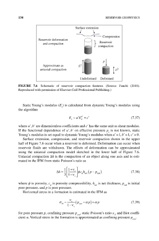
FIGuRE 7.6 Schematic of reservoir compaction features. (Source: Fanchi (2010).
Reproduced with permission of Elsevier‐Gulf Professional Publishing.)
Static Young’s modulus (E ) is calculated from dynamic Young’s modulus using
s
the algorithm
aE +
E = ′ b′ c′ (7.37)
s
d
where a′, b′ are dimensionless coefficients and c′ has the same unit as shear modulus.
If the functional dependence of a′, b′ on effective pressure p is not known, static
e
Young’s modulus is set equal to dynamic Young’s modulus when ′ =a 1, b ′ = c1, ′ = 0.
Surface extension, compression, and reservoir compaction shown in the upper
half of Figure 7.6 occur when a reservoir is deformed. Deformation can occur when
reservoir fluids are withdrawn. The effects of deformation can be approximated
using the uniaxial compaction model sketched in the lower half of Figure 7.6.
Uniaxial compaction Δh is the compaction of an object along one axis and is esti-
mated in the IFM from static Poisson’s ratio as
1 1 +ν
−
∆h = s φ c h ( p p ) (7.38)
init
φ net
3 1 −ν s
where ϕ is porosity, c is porosity compressibility, h is net thickness, p is initial
ϕ
init
net
pore pressure, and p is pore pressure.
Horizontal stress in a formation is estimated in the IFM as
ν
σ = s ( p con −α p ) +α p (7.39)
H
1 −ν s
for pore pressure p, confining pressure p , static Poisson’s ratio ν , and Biot coeffi-
con
s
cient α. Vertical stress in the formation is approximated as confining pressure p .
con