
Page 162 - Introduction to Petroleum Engineering
P. 162
THE DRILLING PROCESS 149
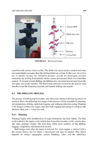
BOP
Annular BOP
Blind shear ram
Pipe ram
Kill line
Casing head
FIGuRe 8.9 Blowout preventer.
manifold with various chokes in line. The choke line can be used to control wells that
encounter higher pressures than the drilling fluid can contain. In this case, the well is
out of balance because the formation pressure exceeds the hydrostatic pressure
exerted by the drilling fluid and the chokes release pressurized fluids in a controlled
manner. To resume normal drilling, the drilling crew circulates heavier mud down the
drill pipe and up the annulus. The hydrostatic pressure exerted by the heavier mud
should exceed the formation pressure and normal drilling can resume.
8.3 THe DRILLING PROCeSS
The process of drilling begins months, and often years, before a drilling rig arrives on
location. Here, the following five stages of the process will be considered: planning,
site preparation, drilling, open‐hole logging, and setting production casing. Planning
is the longest of these five stages, and open‐hole logging and setting of casing are the
shortest, often just 1–3 days for each.
8.3.1 Planning
Planning begins with identification of target formations and their depths. The data
used to identify the target could include data from offset (nearby) wells, seismic data,
and other geologic insight. The data from offset wells includes all the drilling,
logging, completion, and production records.
Well design starts after the target is selected. For some targets, a vertical well is
the correct choice; but for others, a directional well may be needed. That choice
depends on surface topography, surface buildings, lakes, and the subsurface