
Page 175 - Introduction to Petroleum Engineering
P. 175
162 WELL LOGGING
Header Header
Scale Scale Scale Scale Scale
Track Track Track Track Track
1 2 1 2 3
Depth track
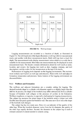
FIGuRE 9.1 Well log format.
Logging measurements are recorded as a function of depth, as illustrated in
Figure 9.1. The left‐hand side of the figure illustrates a well log with two measurement
tracks and another with three measurement tracks. Both well logs have a track for
depth. The measurement tracks display measurement values relative to a scale that is
suitable for the measurement. More than one measurement may be displayed in each
measurement track. The header contains information about the well (such as name,
location, and owner), the logging run (such as date, logging company, and tool
description), and the scales for the measurement at the top of the tracks.
Performance of logging tools depends on the logging environment. The environ-
ment includes such factors as rock type and structure, fluids in the well and adjacent
formation, temperature and pressure. Some features of the logging environment are
discussed below.
9.1.1 Wellbore and Formation
The wellbore and adjacent formations are a complex setting for logging. The
desired borehole shape is a cylinder with diameter equal to or slightly larger than the
drill bit. In practice, the shape of the borehole may differ substantially from a cylinder
because of borehole wall collapse or the presence of cavities in the formation.
Wellbore roughness, or rugosity, is especially challenging for logging measurements.
The caliper log measures the actual shape of the borehole using a caliper tool with
flexible arms that push against the borehole wall. The arms move in or out as the shape
of the borehole wall changes.
The caliper log has two main uses. First, it is an indicator of the quality of the
other logs. When the borehole diameter varies from the bit diameter, the quality of
the other logs rapidly declines. Second, the diameter in the caliper log is used to
estimate amount of cement needed to cement casing.