
Page 213 - Introduction to Petroleum Engineering
P. 213
200 WELL COMPLETIONS
The procedure for estimating fracture length is illustrated by the following example.
Example 10.11 Fracture Length
If the relative conductivity of a fracture is 1000 in., what length should be spec-
ified for the fracture?
Answer
For this low relative conductivity, the ratio of productivity indices is about 1.8
.
for L L/ q = 01, and it is very insensitive to increasing fracture length. Rather
f
than worry about fracture length, it would be better to find how to increase
relative conductivity—either by making a wider fracture or providing for
higher fracture permeability. If relative conductivity could be increased to
10 000 in., then L /L as high as 0.4 could make sense, allowing for a ratio of
f
q
productivity indices as high as about 5.6.
The relative conductivity of a fracture depends on two things that a petroleum
engineer can control or influence during frack design: the permeability of the prop-
pant pack and the width of the fracture, which relates to the amount of proppant
placed in the fracture. The permeability of the proppant pack varies with size of the
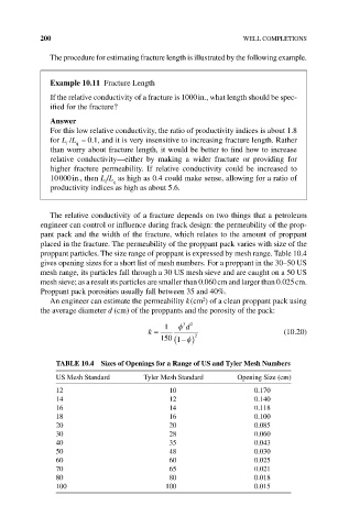
proppant particles. The size range of proppant is expressed by mesh range. Table 10.4
gives opening sizes for a short list of mesh numbers. For a proppant in the 30–50 US
mesh range, its particles fall through a 30 US mesh sieve and are caught on a 50 US
mesh sieve; as a result its particles are smaller than 0.060 cm and larger than 0.025 cm.
Proppant pack porosities usually fall between 35 and 40%.
2
An engineer can estimate the permeability k (cm ) of a clean proppant pack using
the average diameter d (cm) of the proppants and the porosity of the pack:
1 φ 3 d 2
k = 2 (10.20)
150 (1 − ) φ
TAbLE 10.4 Sizes of Openings for a Range of US and Tyler Mesh Numbers
US Mesh Standard Tyler Mesh Standard Opening Size (cm)
12 10 0.170
14 12 0.140
16 14 0.118
18 16 0.100
20 20 0.085
30 28 0.060
40 35 0.043
50 48 0.030
60 60 0.025
70 65 0.021
80 80 0.018
100 100 0.015