
Page 49 - Introduction to Transfer Phenomena in PEM Fuel Cells
P. 49
38 Introduction to Transfer Phenomena in PEM Fuel Cells
It essentially consists of a membrane electrode assembly (MEA) with a
thickness of 500 to 600 µm (see Figure 1.4). Electrons flow through a
conductor if necessary. The anode and the cathode include a catalyst for
producing electricity from the chemical reaction.
The chemical energy of the reactants is converted into electrical energy,
heat and water by the catalyst (electrode with a mixture of carbon and
platinum). The fuel (hydrogen) and the oxidant (oxygen) move to the
catalyst layers where the chemical reaction occurs. It must be noted that the
water and residual heat produced by the fuel cell must be constantly
removed as these residues may present risks for the battery [HOR].
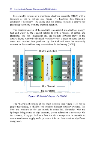
Figure 1.15. Detailed diagram of a PEMFC
The PEMFC cell consists of five main elements (see Figure 1.15). For its
proper functioning, a PEMFC cell requires different auxiliary systems. The
flow and pressure of the gas supply is controlled. Generally, with the
hydrogen being stored at high pressure, system relaxation is necessary. On
the contrary, if oxygen is drawn from the air, a compressor is essential to
ensure continuous supply under pressure, this can have a rather significant
energy cost.