
Page 114 - Know and Understand Centrifugal Pumps
P. 114
The System Curve
H
FEET
0 w Q
GPM
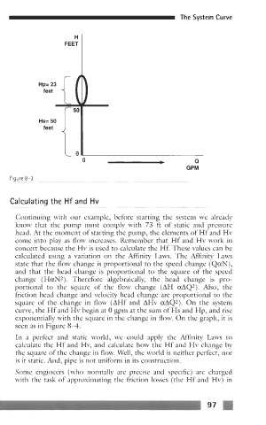
Figure 8-3
~~ ~- -
Calculating the Hf and Hv
~~ ~~ ~~~
Continuing with our example, before starting the system we already
know that the pump must comply with 73 ft of static and pressure
head. At the moment of starting the pump, the elements of Hf and Hv
come into play as flow increases. Remember that Hf and Hv work in
concert because the Hv is used to calculate the Hf. These values can be
calculated using a variation on the Affinity Laws. The Affinity Laws
state that the flow change is proportional to the speed change (QaN),
and that the head change is proportional to the square of the speed
change (HaN2). Therefore algebraically, the head change is pro-
portional to the square of the flow change (AH aAQ2). Also, the
friction head change and velocity head change are proportional to the
square of the change in flow (AHf and AHv aAQ2). On the system
curve, the Hf and Hv begin at 0 gpm at the sum of Hs and Hp, and rise
exponentially with the square in the change in flow. On the graph, it is
seen as in Figure 84.
In a perfect and static world, we could apply the Affinity Laws to
calculate the Hf and Hv, and calculate how the Hf and Hv change by
the square of the change in flow. Well, the world is neither perfect, nor
is it static. And, pipe is not uniform in its construction.
Some engineers (who normally are precise and specific) are charged
with the task of approximating the friction losses (the Hf and Hv) in
97 FI