
Page 118 - Know and Understand Centrifugal Pumps
P. 118
The System Curve
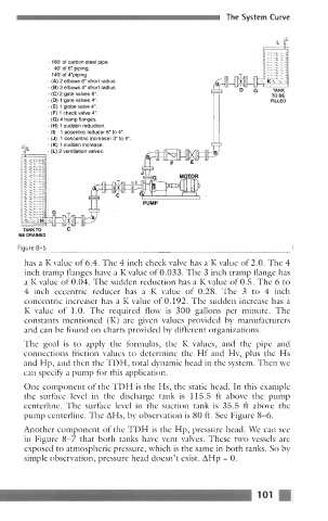
- 180 of carbon steel pipe.
- 40 of 6' piping.
- 140 of Vpiping.
- (A) 2 elbows 6" short radius.
- (B) 3 elbows 4" short radius.
- (C) 2 gate valves 6".
- (D) 1 gate valves 4".
1
- (E) globe valve 4".
- (F) 1 check valve 4".
- (G) 4 tramp flanges.
- (H) 1 sudden reduction.
- (I) 1 eccentric reducer 6" to 4".
- (J) 1 concentrii increaser 3' to 4".
- (K) 1 sudden increase.
- (L) 2 ventilation valves.
1 I
PUMP
TANKTO C
BE DRAINED
Fiaure 8-5
has a K value of 6.4. The 4 inch check valve has a K value of 2.0. The 4
inch tramp flanges have a K value of 0.033. The 3 inch tramp flange has
a K value of 0.04. The sudden reduction has a K value of 0.5. The 6 to
4 inch eccentric reducer has a K value of 0.28. The 3 to 4 inch
concentric increaser has a K value of 0.192. The sudden increase has a
K value of 1.0. The required flow is 300 gallons per minute. The
constants mentioned (K) are given values provided by manufacturers
and can be found on charts provided by different organizations.
The goal is to apply the formulas, the K values, and the pipe and
connections friction values to determine the Hf and Hv, plus the Hs
and Hp, and then the TDH, total dynamic head in the system. Then we
can specify a pump for this application.
One component of the TDH is the Hs, the static head. In this example
the surface level in the discharge tank is 115.5 ft above the pump
centerline. The surface level in the suction tank is 35.5 ft above the
pump centerline. The AHs, by observation is 80 ft. See Figure 8-6.
Another component of the TDH is the Hp, pressure head. We can see
in Figure 8-7 that both tanks have vent valves. These two vessels are
exposed to atmospheric pressure, which is the same in both tanks. So by
simple observation, pressure head doesn't exist. AHp = 0.
101