
Page 163 - Know and Understand Centrifugal Pumps
P. 163
Know and Understand Centrifugal Pumps
Rim and face alignment
This method is most useful when only one of the shafts can be rotated
for the alignment procedure, or when the two shaft ends are very close
to each other. Obtain the displacement readings with the dial on the
rim (OD) of the coupling and the coupling face. Project these readings
mathematically or graphically to the motor base to determine the
required adjustments and shims for each foot. This method is not as
precise and may have a built-in error, if the coupling center is eccentric
from the shaft centerline.
Laser a I ig n men t
Laser alignment systems use a transmitter and receiver. The system has a
laser diode and a position sensor on a bracket mounted on one shaft
that emits a weak and safe radio-tagged beam of light. The light ray is
directed toward the other bracket on the other shaft with a reflecting
prism that returns the ray back toward the first bracket into the position
sensor eye.
One shaft is rotated to determine the vertical and horizontal readings as
in the other alignment techniques.
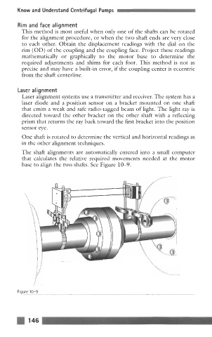
The shaft alignments are automatically entered into a small computer
that calculates the relative required movements needed at the motor
base to align the two shafts. See Figure 10-9.
Fiqure 10-9
146