
Page 162 - Know and Understand Centrifugal Pumps
P. 162
Pump and Motor Alignment
+-$$h-1-
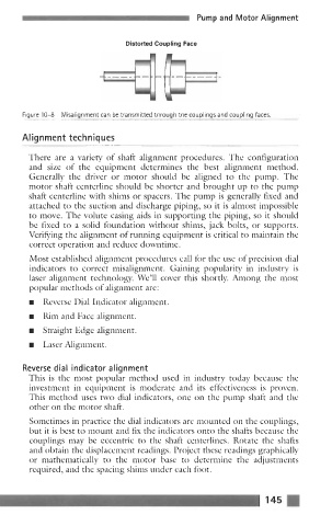
Distorted Coupling Face
~~ Figure 10-8 Misalignment can be transmitted through the couplings and coupling faces.
~
Alignment techniques
There are a variety of shaft alignment procedures. The configuration
and size of the equipment determines the best alignment method.
Generally the driver or motor should be aligned to the pump. The
motor shaft centerline should be shorter and brought up to the pump
shaft centerline with shims or spacers. The pump is generally fixed and
attached to the suction and discharge piping, so it is almost impossible
to move. The volute casing aids in supporting the piping, so it should
be fixed to a solid foundation without shims, jack bolts, or supports.
Verifying the alignment of running equipment is critical to maintain the
correct operation and reduce downtime.
Most established alignment procedures call for the use of precision dial
indicators to correct misalignment. Gaining popularity in industry is
laser alignment technology. We’ll cover this shortly. Among the most
popular methods of alignment are:
rn Reverse Dial Indicator alignment.
rn Rim and Face alignment.
rn Straight Edge alignment.
rn Laser Alignment.
Reverse dial indicator alignment
This is the most popular method used in industry today because the
investment in equipment is moderate and its effectiveness is proven.
This method uses two dial indicators, one on the pump shaft and the
other on the motor shaft.
Sometimes in practice the dial indicators are mounted on the couplings,
but it is best to mount and fix the indicators onto the shafts because the
couplings may be eccentric to the shaft centerlines. Rotate the shafts
and obtain the displacement readings. Project these readings graphically
or mathematically to the motor base to determine the adjustments
required, and the spacing shims under each foot.