Page 188 -
P. 188

243_MasterPieces_04a.qxd  4/18/03  7:05 PM  Page 160


           160    Masterpiece 4 • PneumADDic II


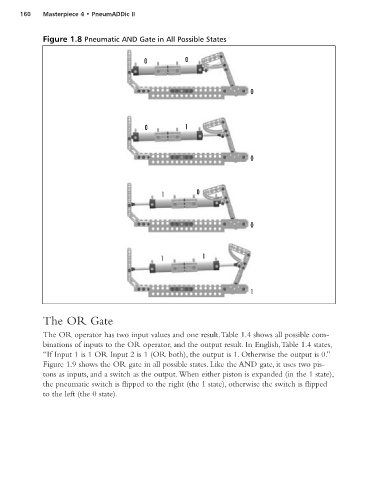
                  Figure 1.8 Pneumatic AND Gate in All Possible States


                                                0           0


                                                                               0


                                                0           1


                                                                               0


                                                     1         0


                                                                               0


                                                     1           1


                                                                               1


                  The OR Gate
                  The OR operator has two input values and one result.Table 1.4 shows all possible com-
                  binations of inputs to the OR operator, and the output result. In English,Table 1.4 states,
                  “If Input 1 is 1 OR Input 2 is 1 (OR both), the output is 1. Otherwise the output is 0.”
                  Figure 1.9 shows the OR gate in all possible states. Like the AND gate, it uses two pis-
                  tons as inputs, and a switch as the output. When either piston is expanded (in the 1 state),
                  the pneumatic switch is flipped to the right (the 1 state), otherwise the switch is flipped
                  to the left (the 0 state).
   183   184   185   186   187   188   189   190   191   192   193