
Page 98 - Lindens Handbook of Batteries
P. 98
FACTORS AFFECTING BATTERY PERFORMANCE 3.17
3.2.10 Charging Voltage
If a rechargeable battery is used (for example, as a standby
power source) in conjunction with another energy source Charge
that is permanently connected in the operating circuit,
allowance must be made for the battery and equipment to
tolerate the voltage of the battery on charge. Figure 3.19
shows the charge and discharge characteristics of such a
battery. The specific voltage and the voltage profile on Voltage
charge depend on such factors as the battery system, charge Discharge
rate, temperature, and so on.
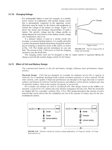
If a primary battery is used in a similar circuit (for
example, as memory backup battery), it is usually advisable
to protect the primary battery from being charged by includ-
ing an isolating or protective diode in the circuit, as shown Time
in Fig. 3.20. Two diodes provide redundancy in case one FIGURE 3.19 Typical voltage profile on
fails. The resistor in Fig. 3.20b serves to limit the charging charge and discharge.
current in case the diode fails.
The charging source must also be designed so that its output current is regulated during the
charge to provide the needed charge control for the battery.
3.2.11 Effect of Cell and Battery Design
The constructional features of the cell and battery strongly influence their performance charac-
teristics.
Electrode Design. Cells that are designed, for example, for optimum service life or capacity at
relatively low or moderate discharge loads contain maximum quantities of active material. On the
other extreme, cells capable of high-rate performance are designed with large electrode or reaction
surfaces and features to minimize internal resistance and enhance current density (amperes per area
of electrode surface), often at the expense of capacity or service life.
For example, two designs are used in cylindrical cells. One design, known as the bobbin con-
struction, is typical for zinc-carbon and some alkaline-manganese dioxide cells. Here the electrodes
are shaped into two concentric cylinders (Fig. 3.21a). This design maximizes the amount of active
material that can be placed into the cylindrical can, but at the expense of surface area for the elec-
trochemical reaction.
FIGURE 3.20 Protective circuits for memory backup applications. (a) Using two diodes. (b) Using
diode and resistor.