
Page 241 - Lindens Handbook of Batteries
P. 241
ZINC-CARBON BATTERIES—LECLANCHÉ AND ZINC CHLORIDE CELL SYSTEMS 9.35
contributor which effects delta V is the activity at the zinc surface, which is dependent on both
zinc particle size and amount of reaction product present. The polarization effect occurs when
the load is held for some time period, as in the case of charging the camera’s strobe circuit.
Total resistance is then a summation of the two resistances—that is, the internal resistance of
the battery and the resistance due to polarization effects, the latter being very time sensitive.
To minimize polarization effect resistance, the pulse period for delta V measurements was
minimized.
The 56-day point is of interest, as that is the normal age when the battery is released for assembly
into film packs. At that time, every battery is measured for electrical characteristics and defective
ones are screened.
The total internal resistance is expressed by the following:
R = R + R p
i
t
where R = battery internal resistance
i
R = polarization resistance effect
p
For the P-80 battery, R was 0.50 ohms and the R was 0.12 ohms.
i p
• Capacity: The capacity simulator mimics the energy used to charge the camera strobe. The pulse
consists of an open-circuit voltage at rest, followed by a pulse at a 2 A load to result in a 50 watt-
second (50 Ws) pulse. The 50 Ws cycle test is maintained until the final CCV reaches the 3.7
cutoff voltage, where the number of cycles is determined.
During the time while the 50 Ws load is maintained, the polarization drop occurs. The time to
produce the 50 Ws increases with each cycle as the battery is “consumed.” A 30 s rest between cycles
is used. Initially, the voltage drop is fairly constant; however, near the end of the test, the resistance
increases. The test is maintained to 3.7 V to indicate the cutoff point of the camera.
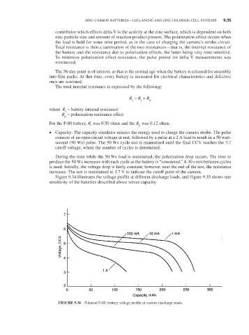
Figure 9.34 illustrates the voltage profile at different discharge loads, and Figure 9.35 shows rate
sensitivity of the batteries described above versus capacity.
FIGURE 9.34 Polaroid P-80; battery voltage profile at various discharge loads.