
Page 47 - Low Temperature Energy Systems with Applications of Renewable Energy
P. 47
Principles and operation of refrigeration and heat pump systems 35
where V ¼ velocity, L ¼ characteristic length, r ¼ density, l ¼ thermal conductivity,
DT ¼ temperature difference.
• Low heat capacity of liquid and high heat capacity of superheated vapor;
• Saturated vapor curve has positive slope in temperature-entropy coordinates;
• Low condensation pressure and low boiling point temperature at atmospheric pressure;
• High thermal conductivity and low viscosity.
• Operational
Thermochemical stability, chemical compatibility with materials, nonflammability, non-
toxicity and non-explosion hazard.
• Economic
Availability of commodity production and reasonable prices.
• Ecological
Ozone safety and low potential of global warming.
1.7 Operating modes of heat pumps
1.7.1 Flexible heating and cooling
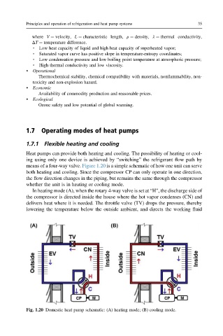
Heat pumps can provide both heating and cooling. The possibility of heating or cool-
ing using only one device is achieved by “switching” the refrigerant flow path by
means of a four-way valve. Figure 1.20 is a simple schematic of how one unit can serve
both heating and cooling. Since the compressor CP can only operate in one direction,
the flow direction changes in the piping, but remains the same through the compressor
whether the unit is in heating or cooling mode.
In heating mode (A), when the rotary 4-way valve is set at “H”, the discharge side of
the compressor is directed inside the house where the hot vapor condenses (CN) and
delivers heat where it is needed. The throttle valve (TV) drops the pressure, thereby
lowering the temperature below the outside ambient, and directs the working fluid
Fig. 1.20 Domestic heat pump schematic: (A) heating mode; (B) cooling mode.