
Page 64 - Low Temperature Energy Systems with Applications of Renewable Energy
P. 64
Characteristics of low-temperature energy sources for heat pumps 53
Table 2.2 Range of values for soil porosity.
Soil Porosity, % Soil Porosity, %
Clay 45e55 Sandstone 5e30
Mule 35e50 Limestone 1e20
Sand 25e40 Shale 0e10
Gravel 25e40 Rock <1
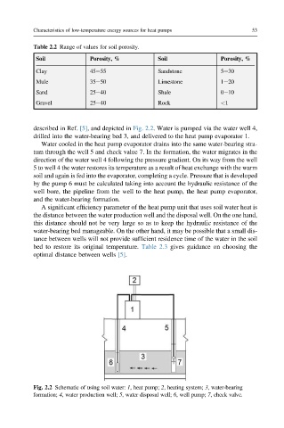
described in Ref. [5], and depicted in Fig. 2.2. Water is pumped via the water well 4,
drilled into the water-bearing bed 3, and delivered to the heat pump evaporator 1.
Water cooled in the heat pump evaporator drains into the same water-bearing stra-
tum through the well 5 and check value 7. In the formation, the water migrates in the
direction of the water well 4 following the pressure gradient. On its way from the well
5 to well 4 the water restores its temperature as a result of heat exchange with the warm
soil and again is fed into the evaporator, completing a cycle. Pressure that is developed
by the pump 6 must be calculated taking into account the hydraulic resistance of the
well bore, the pipeline from the well to the heat pump, the heat pump evaporator,
and the water-bearing formation.
A significant efficiency parameter of the heat pump unit that uses soil water heat is
the distance between the water production well and the disposal well. On the one hand,
this distance should not be very large so as to keep the hydraulic resistance of the
water-bearing bed manageable. On the other hand, it may be possible that a small dis-
tance between wells will not provide sufficient residence time of the water in the soil
bed to restore its original temperature. Table 2.3 gives guidance on choosing the
optimal distance between wells [5].
Fig. 2.2 Schematic of using soil water: 1, heat pump; 2, heating system; 3,water-bearing
formation; 4, water production well; 5, water disposal well; 6,well pump; 7, check valve.