
Page 135 - MEMS Mechanical Sensors
P. 135
124 Pressure Sensors
when designing the device as a whole at the outset. For a more detailed analysis of
diaphragm behavior, the author recommends the work of Di Giovanni [3].
Pressure applied to one (or both) side(s) of the diaphragm will cause it to deflect
until the elastic force balances the pressure. The pressure range of a given diaphragm
will depend upon its dimensions (surface area and thickness), geometry, edge condi-
tions, and the material from which it is made. Traditional metal diaphragm pressure
sensors are made from a range of materials such as stainless steels 316L, 304, 17-4
PH, PH 15-7 Mo, titanium, nickel alloys, and beryllium copper. The metals are
characterized by good elastic properties and media compatibility.
In the case of traditional sensors, diaphragms are the simplest sensor element to
manufacture, they are the least sensitive to vibrations, they offer the best dynamic
response, and they are compatible with simple forms of overload protection. How-
ever, the deflection associated with diaphragms is much less than, for example,
Bourdon tubes. Therefore, electromechanical transduction mechanisms may be
employed to measure the deflection rather than the mechanical linkages associated
with Bourdon tubes.
Metal diaphragms are typically circular and may incorporate corrugations to
modify diaphragm characteristics. The behavior of a diaphragm will depend upon
many factors, such as the edge conditions and the deflection range compared to
diaphragm thickness. The edge conditions of a diaphragm will depend upon the
method of manufacture and the geometry of the surrounding structure. It will vary
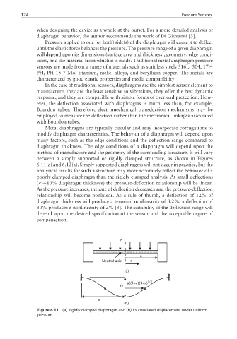
between a simply supported or rigidly clamped structure, as shown in Figures
6.11(a) and 6.12(a). Simply supported diaphragms will not occur in practice, but the
analytical results for such a structure may more accurately reflect the behavior of a
poorly clamped diaphragm than the rigidly clamped analysis. At small deflections
(<∼10% diaphragm thickness) the pressure-deflection relationship will be linear.
As the pressure increases, the rate of deflection decreases and the pressure-deflection
relationship will become nonlinear. As a rule of thumb, a deflection of 12% of
diaphragm thickness will produce a terminal nonlinearity of 0.2%; a deflection of
30% produces a nonlinearity of 2% [3]. The suitability of the deflection range will
depend upon the desired specification of the sensor and the acceptable degree of
compensation.
P
a
Neutral axis r
(a)
ν
ν
a((1+ )(3+ ) 1/2
y
0
a
(b)
Figure 6.11 (a) Rigidly clamped diaphragm and (b) its associated displacement under uniform
pressure.