
Page 136 - MEMS Mechanical Sensors
P. 136
6.4 Diaphragm-Based Pressure Sensors 125
P
(a)
y 0
(b)
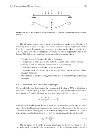
Figure 6.12 (a) Simply supported diaphragm and (b) its associated displacement under uniform
pressure.
The following two sections present analytical equations for the deflection and
resulting stress of rigidly clamped and simply supported metal diaphragms. These
have been grouped according to the degree of deflection in relation to thickness,
denoted small deflection diaphragms, medium deflection diaphragms, and mem-
branes. The following equations assume the following assumptions:
• The diaphragm is flat and of uniform thickness.
• The material is homogenous and isotropic (silicon will be covered later).
• Pressure is applied normally to the plane of the diaphragm.
• The elastic limit of the material is not exceeded.
• The thickness of the diaphragm is not too thick (e.g., maximum 20% of dia-
phragm diameter).
• Deformation is due to bending, the neutral axis of the diaphragm experiences
no stress.
6.4.1 Analysis of Small Deflection Diaphragm
For small deflection diaphragms the maximum deflection is 30% of diaphragm
thickness. The deflection y at radial distance r of a round diaphragm under a uni-
form pressure P, rigidly clamped as shown in Figure 6.11(a), is given by
( −ν
31 2 )P 2
2
y = (a − r 2 ) (6.9)
16 Eh 3
where h is the diaphragm thickness, E and ν are the Young’s modulus and Poisson’s
ratio of the diaphragm material, respectively, and a is the radius of the diaphragm.
The maximum deflection y will occur at the diaphragm center where r = 0. Assum-
0
ing a common value for metals of υ = 0.3, the maximum deflection is given by
.
01709 Pa 4
y = (6.10)
0 3
Eh
The deflection of a rigidly clamped diaphragm is shown in Figure 6.11(b).
As mentioned previously, the measurement of the deflection associated with