
Page 139 - MEMS Mechanical Sensors
P. 139
128 Pressure Sensors
Ey 2
σ =096 0 (6.24)
.
r
a 2
E 3 − ν r 2
2
σ = 0 −3 (6.25)
t
2
2
4 a 1 − ν a
Other factors such as tensioned membranes or the inclusion of rigid centers are
beyond the scope of this book.
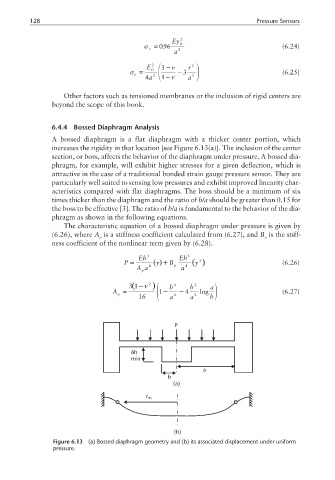
6.4.4 Bossed Diaphragm Analysis
A bossed diaphragm is a flat diaphragm with a thicker center portion, which
increases the rigidity in that location [see Figure 6.13(a)]. The inclusion of the center
section, or boss, affects the behavior of the diaphragm under pressure. A bossed dia-
phragm, for example, will exhibit higher stresses for a given deflection, which is
attractive in the case of a traditional bonded strain gauge pressure sensor. They are
particularly well suited to sensing low pressures and exhibit improved linearity char-
acteristics compared with flat diaphragms. The boss should be a minimum of six
times thicker than the diaphragm and the ratio of b/a should be greater than 0.15 for
the boss to be effective [3]. The ratio of b/a is fundamental to the behavior of the dia-
phragm as shown in the following equations.
The characteristic equation of a bossed diaphragm under pressure is given by
(6.26), where A is a stiffness coefficient calculated from (6.27), and B is the stiff-
p p
ness coefficient of the nonlinear term given by (6.28).
Eh 3 Eh 3
3
P = () y + B p () (6.26)
y
Aa 4 a 4
p
( −ν
31 2 ) b 4 b 2 a
A = 1 − −4 log (6.27)
p
16 a 4 a 2 b
P
6h
min
a
b
(a)
r m
(b)
Figure 6.13 (a) Bossed diaphragm geometry and (b) its associated displacement under uniform
pressure.