
Page 143 - MEMS Mechanical Sensors
P. 143
132 Pressure Sensors
1
2
E
.
f =1654 ρ ( −ν 2 ) ha 2 (6.36)
1
n
The amount of damping present will depend not only on the diaphragm design
but also its packaging and surroundings. As a rough guide, resonant frequencies of
typical diaphragms should range between ~80 kHz for a 1-bar device to 575 kHz for
a 40-bar device [14]. Higher frequency devices have been developed; for example,
the Entran EPIH Micro Miniature range high-frequency pressure sensor series offers
a maximum resonant frequency of 1.7 MHz for the 20-bar device [15]. For this
series, the pressurized media is in direct contact with the micromachined silicon
structure, and therefore it is suitable only for dry gas or some noncorrosive fluid
applications. The introduction of a stainless steel barrier diaphragm lowers the reso-
nant frequency to 45 kHz for a 17-bar device [16].
6.5.2 Piezoresistive Pressure Sensors
The piezoresistive nature of silicon makes the use of diffused or implanted resistors
an obvious and straightforward technique for measuring the strain in a
micromachined silicon diaphragm. The piezoresistive effect of silicon was first
exploited by bonding silicon strain gauges to metal diaphragms [7], but this is an
unsatisfactory approach given the thermal mismatch between the metal, adhesive
layer, and silicon. Diaphragms were first micromachined into the silicon itself by
mechanical spark erosion and wet isotropic etching [8]. This was not a batch
approach and therefore device costs were high. The use of anisotropic etching, anodic
and fusion bonding, ion implanted strain gauges, and surface micromachining have
since reduced the size and improved the accuracy of piezoresistive pressure sensors.
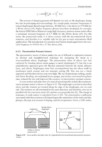
A cross-section and plan view of a typical anisotropically etched silicon piezore-
sistive pressure sensor is shown in Figure 6.15. The diaphragm is etched as described
above and the resistors are located along the edge of the diaphragm, one on each
side. The resistors are all orientated in the same direction, and therefore, two are in
parallel with the maximum strain (R) and two are perpendicular (R ). The change in
l t
resistance of each resistor is calculated from (5.10). The piezoresistive coefficients
associated with these resistors will depend upon the orientation of the wafer and dia-
phragm, the type and amount of doping, and the temperature. Given a (100) wafer,
Etched silicon
Implanted diaphragm
R l
R t
Glass silicon
constraint
Drilled or etched
pressure port
Figure 6.15 Cross-section and plan view of a typical bulk micromachined piezoresistive pressure
sensor.