
Page 142 - MEMS Mechanical Sensors
P. 142
6.5 MEMS Technology Pressure Sensors 131
processes. The most common fabrication method is anisotropic wet silicon etching,
which allows good control over diaphragm dimensions and is a batch process capa-
ble of producing hundreds of devices simultaneously across a group of wafers.
When combined with a (100) wafer orientation, a wet potassium hydroxide (KOH)
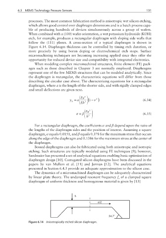
etch, for example, produces a rectangular diaphragm with sloping side walls that
follow the (111) planes. A cross-section of a typical diaphragm is shown in
Figure 6.14. Diaphragm thickness can be controlled by timing etch duration, or
more precisely by using boron doping or electrochemical etch stops. Surface
micromachining techniques are becoming increasing applied since they offer the
opportunity for reduced device size and compatibility with integrated electronics.
When modeling complex micromachined structures, finite element (FE) pack-
ages such as those described in Chapter 3 are normally employed. Diaphragms
represent one of the few MEMS structures that can be modeled analytically. Since
the diaphragm is rectangular, the characteristic equations will differ from those
describing the circular case above. The characterizing equations for a rectangular
diaphragm, where a is the length of the shorter side, and with rigidly clamped edges
and small deflections are given next.
Pa 4
y =α 3 (1−ν 2 ) (6.34)
0
Eh
Pa 2
σ = β (6.35)
h 2
For a rectangular diaphragm, the coefficients α and β depend upon the ratio of
the lengths of the diaphragm sides and the position of interest. Assuming a square
diaphragm, α equals 0.0151, and β equals 0.378 for the maximum stress that occurs
along the edge of the diaphragm and 0.1386 for the maximum stress at the center of
the diaphragm.
Bossed diaphragms can also be fabricated using both anisotropic and isotropic
etching. Such structures are typically modeled using FE techniques [9]; however,
Sandmaier has presented a set of analytical equations enabling basic optimization of
diaphragm design [10]. Corrugated silicon diaphragms have been discussed in the
papers by van Mullem et al. [11] and Jerman [12]. The analytical equations
presented in Section 6.4.5 provide an adequate approximation to the silicon case.
The dynamics of a micromachined diaphragm can be adequately characterized
by linear plate theory. The undamped resonant frequency f of a clamped square
n
diaphragm of uniform thickness and homogenous material is given by [13]
h
a/2
54.7 o
Figure 6.14 Anisotropically etched silicon diaphragm.