
Page 144 - MEMS Mechanical Sensors
P. 144
6.5 MEMS Technology Pressure Sensors 133
the edges of the diaphragm will be in the (110) directions. The piezoresistive coeffi-
cients of p- and n-type silicon are presented graphically by Kanda [17]. Assuming
p-type doping, which produces the largest and most linear piezoresistive effect, π
l
2
and π are equal and opposite at +/−69 m /N, respectively. From (5.10) it can be
t
seen that the resistor orientation shown in Figure 6.15 will produce equal and oppo-
site changes in the resistance of the two pairs of resistors. Placing the two pairs of
resistors on opposite sides of a full bridge circuit will therefore maximize the sensi-
tivity of the sensor to strains arising from pressure induced deflection of the dia-
phragm. The stress can be calculated from (6.35) and for a full bridge the fractional
bridge output is given by (6.37). This is the most common resistor arrangement and
has been modeled analytically extensively [18–20].
∆V (∆RR ) − (∆RR )
= l t (6.37)
)
V 2 + (∆RR + (∆RR )
l t
Piezoresistive pressure sensors in the form described above have been commer-
cially available for many years. Manifold absolute pressure sensors are an estab-
lished application of these devices in the automotive industry. An example of such a
device has been developed by Motorola and has been described in detail in [21].
Other, more recent automotive applications based upon piezoresistive sensing
include diesel injection pressure [22] and exhaust gas recirculation systems [23].
Circular diaphragms are less common and have been analyzed by Matsuoka et al.
[24]. Variations on the theme involve changes to the diaphragm structure (including
bossed and ribbed diaphragms), temperature compensation techniques, and the use
of alternative fabrication processes.
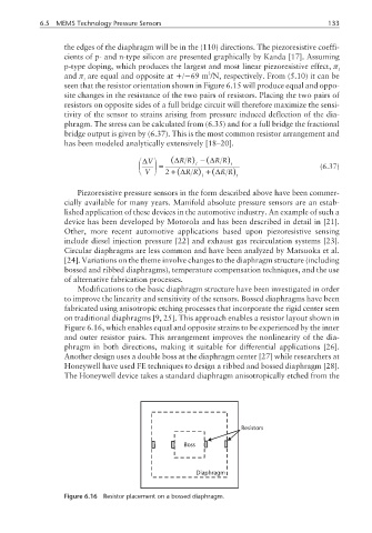
Modifications to the basic diaphragm structure have been investigated in order
to improve the linearity and sensitivity of the sensors. Bossed diaphragms have been
fabricated using anisotropic etching processes that incorporate the rigid center seen
on traditional diaphragms [9, 25]. This approach enables a resistor layout shown in
Figure 6.16, which enables equal and opposite strains to be experienced by the inner
and outer resistor pairs. This arrangement improves the nonlinearity of the dia-
phragm in both directions, making it suitable for differential applications [26].
Another design uses a double boss at the diaphragm center [27] while researchers at
Honeywell have used FE techniques to design a ribbed and bossed diaphragm [28].
The Honeywell device takes a standard diaphragm anisotropically etched from the
Resistors
Boss
Diaphragm
Figure 6.16 Resistor placement on a bossed diaphragm.