
Page 149 - MEMS Mechanical Sensors
P. 149
138 Pressure Sensors
the pressure-sensitive diaphragm. This technique greatly reduces the cross-
sensitivity to accelerations.
The main drawbacks associated with the capacitive approach are the inherently
nonlinear output of the sensor and the complexity of electronics (compared with the
resistive bridge). Assuming parallel deflection in the flexible diaphragm, the change
in capacitance is inversely proportional to the gap height. In addition to this, a basic
diaphragm such as that shown in Figure 6.21 will bend as it deflects. The diaphragm
will therefore no longer be parallel to the fixed electrode and this introduces a fur-
ther nonlinearity in the sensor output. The use of bossed diaphragms will mitigate
this effect to some degree [57, 58]. Another linearizing approach is to pattern the
electrodes such that the sensing capacitance is measured from a particular part of the
diaphragm. Maximum deflection occurs at the diaphragm center but this is also the
location of maximum nonlinearity. By sensing the capacitance at an annulus
removed a short distance from the diaphragm center, non-linearity is reduced but at
the expense of sensitivity [59, 60]. Another approach, again at the expense of sensi-
tivity, is to clamp the center of the diaphragm such that the pressure-sensitive struc-
ture becomes a ring shape. The sensitivity of such a structure is reported to be half
that of an equivalent flat plate diaphragm, but nonlinearity falls to 0.7% FS [61].
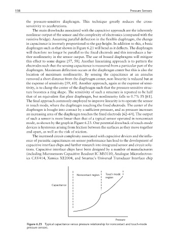
The final approach commonly employed to improve linearity is to operate the sensor
in touch mode, where the diaphragm touching the fixed electrode. The center of the
diaphragm is bought into contact by a sufficient pressure, and as pressure increases
an increasing area of the diaphragm touches the fixed electrode [62–64]. The output
of such a sensor is more linear than that of a typical sensor operated in noncontact
mode, as shown by the graph in Figure 6.23. One potential drawback of touch-mode
devices is hysteresis arising from friction between the surfaces as they move together
and apart, as well as the risk of stiction.
The increased circuit complexity associated with capacitive devices and the influ-
ence of parasitic capacitances on sensor performance has lead to the development of
capacitive interface chips and further research into integrated sensor and circuit solu-
tions. Capacitive interface chips have been designed by a number of manufacturers
(including Microsensors Capacitive Readout IC MS3110, Analogue Microelectron-
ics CAV414, Xemics XE2004, and Smartec’s Universal Transducer Interface chip
Noncontact region Touch mode
region
Capacitance
Pressure
Figure 6.23 Typical capacitance versus pressure relationship for noncontact and touch-mode
pressure sensors.