
Page 219 - MEMS and Microstructures in Aerospace Applications
P. 219
Osiander / MEMS and microstructures in Aerospace applications DK3181_c010 Final Proof page 210 1.9.2005 12:13pm
210 MEMS and Microstructures in Aerospace Applications
rotated, Coriolis forces cause the sense mass to oscillate out of plane. This change is
measured by capacitive plates and is proportional to the rotational rate of the body.
The MEMS three-axis gyro sub-assembly used in the SC is depicted in
Figure 10.2. The specific MEMS inertial sensing instrument used in the ISC is
the TFG14-R3, 20-mm thick gyro fabricated in a silicon-on-insulator process that
incorporates novel features for high performance. Under typical operating condi-
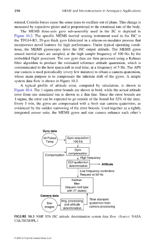
tions, the MEMS gyroscopes drive the ISC output attitude. The MEMS gyros
sensed inertial rates are sampled, at the high sample frequency of 100 Hz, by the
embedded flight processor. The raw gyro data are then processed using a Kalman
filter algorithm to produce the estimated reference attitude quaternion, which is
communicated to the host spacecraft in real time, at a frequency of 5 Hz. The APS
star camera is used periodically (every few minutes) to obtain a camera quaternion,
whose main purpose is to compensate the inherent drift of the gyros. A simple
system data flow is shown in Figure 10.3.
A typical profile of attitude error, computed by simulation, is shown in
Figure 10.4. The 1-sigma error bounds are shown in bold, while the actual attitude
error from one simulated run is shown as a thin line. Since the error bounds are
1-sigma, the error can be expected to go outside of the bound for 32% of the time.
Every 5 min, the gyros are compensated with a fresh star camera quaternion, as
evidenced by the sudden narrowing of the error bounds. Used together as a tightly
integrated sensor suite, the MEMS gyros and star camera enhance each other’s
Gyro data
∆θ Pulses Gyro acquisition
Temp 100 Hz
Gyro
compensation
Compensation
High frequency
ECI quaternion
determination Attitude
Low frequency controllers
Request at 50 Hz
Kalman
filter
(Square root type
with 27 states)
Camera data
Time stamped
Img. processing
Star and attitude quaternion from
images camera processing
determination
FIGURE 10.3 NMP ST6 ISC attitude determination system data flow. (Source: NASA
CALTECH/JPL.)
© 2006 by Taylor & Francis Group, LLC