Page 513 -
P. 513

9-34                                                             MEMS: Design and Fabrication


                               200
                               180
                               160
                               140
                             Pull-in voltage (V)  120         Predicted V


                               100
                                80

                                60
                                                                            10 × 2 cell with
                                                                            epoxy assembly
                                40
                                                                            12.5 × 2 cell with
                                20
                                                                            tape assembly
                                 0
                                    0      1      2      3      4      5      6      7      8
                                                             Mass (g)

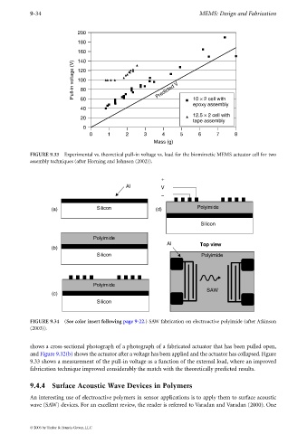
             FIGURE 9.33 Experimental vs. theoretical pull-in voltage vs. load for the biomimetic MEMS actuator cell for two
             assembly techniques (after Horning and Johnson (2002)).


                                                                +
                                                  Al           V
                                                                −

                     (a)               Silicon               (d)             Polyimide


                                                                               Silicon

                                     Polyimide
                                                                  Al           Top view
                     (b)
                                       Silicon                                 Polyimide


                                     Polyimide
                                                                                 SAW
                     (c)
                                       Silicon


             FIGURE 9.34 (See color insert following page 9-22.) SAW fabrication on electroactive polyimide (after Atkinson
             (2003)).


             shows a cross-sectional photograph of a photograph of a fabricated actuator that has been pulled open,
             and Figure 9.32(b) shows the actuator after a voltage has been applied and the actuator has collapsed. Figure
             9.33 shows a measurement of the pull-in voltage as a function of the external load, where an improved
             fabrication technique improved considerably the match with the theoretically predicted results.


             9.4.4 Surface Acoustic Wave Devices in Polymers

             An interesting use of electroactive polymers in sensor applications is to apply them to surface acoustic
             wave (SAW) devices. For an excellent review, the reader is referred to Varadan and Varadan (2000). One


             © 2006 by Taylor & Francis Group, LLC
   508   509   510   511   512   513   514   515   516   517   518