
Page 142 - Machinery Component Maintenance
P. 142
Machinery Foundations and Grouting 125
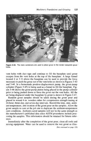
Figure 3-42. The resin containers are used to place grout in the center baseplate grout
holes.
vent holes with duct tape and continue to fill the baseplate until grout
escapes from the vent holes at the top of the baseplate. A large funnel
located 2 or 3 ft above the baseplate can be used to provide the force
necessary to push the grout out of the vent holes as shown in Figures 3-43
and 3-44. In a homemade positive-displacement pump, the grout-pump
cylinder (Figure 3-45) is being used as a funnel to fill the baseplate. Fig-
ure 3-46 shows the grout-pump piston being placed in the pump cylinder
prior to being pushed down to force the grout out the vent holes. All the
air being displaced under the baseplate by grout is shown in Figure 3-47.
Random grout samples should be taken during the grout pour and
placed in waxed 4-in. wooden cubes for compression strength testing at
24-hour, three-day, and seven-day intervals. Record the time, date, ambi-
ent temperature, and location of the grout pour on the samples. Allow the
grout sample to cure at the job site to duplicate the ambient-temperature
cure conditions. Ambient-cured samples will not be the same strength as
the manufacturer’s published data since ASTM procedures include post-
curing the samples. This information should be retained for future refer-
ence.
Immediately after the completion of the grout pour, clean all tools and
mixing equipment. Water can be used to remove the wet grout as illus-
(Text continued on page 128)