
Page 198 - Machinery Component Maintenance
P. 198
180 Machinery Component Maintenance und Repair
Setup 5
MACHINE
----7-
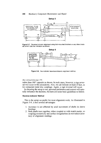
Figure 5-7. Reverse-indicator alignment using face-mounted brackets or any other brack-
ets which hold the indicators as shown.
Setup 6
MACHINE
ELEMENT
TO BE
ADJUSTED
4 4 I
Figure 5-8. Two-indicator face-facedistance alignment method.
(Text continued from page 177)
rather than 180" opposite as shown. In such cases, however, a sign rever-
sal will occur in the calculations. Also, we can indicate on back of face, as
for connected metal disc couplings. Again, a sign reversal will occur.
In choosing the setup to use, personal preference and custom will natu-
rally influence the decision, but here are some basic guidelines to follow.
Reverse-Indicator Method
This is the setup we prefer for most alignment work. As illustrated in
Figure 5-9, it has several advantages:
1. Accuracy is not affected by axial movement of shafts in sleeve
bearings.
2. Both shafts turn together, either coupled or with match marks, so
coupling eccentricity and surface irregularities do not reduce accu-
racy of alignment readings.