
Page 199 - Machinery Component Maintenance
P. 199
Machinery Alignment 181
”
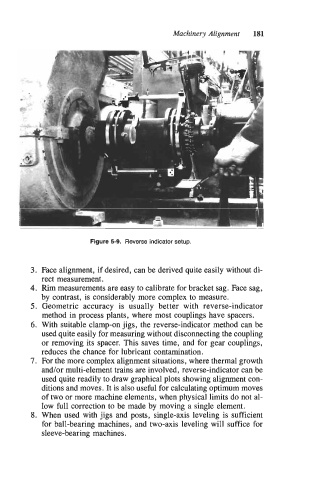
Figure 5-9. Reverse indicator setup.
3. Face alignment, if desired, can be derived quite easily without di-
rect measurement.
4. Rim measurements are easy to calibrate for bracket sag. Face sag,
by contrast, is considerably more complex to measure.
5. Geometric accuracy is usually better with reverse-indicator
method in process plants, where most couplings have spacers.
6. With suitable clamp-on jigs, the reverse-indicator method can be
used quite easily for measuring without disconnecting the coupling
or removing its spacer. This saves time, and for gear couplings,
reduces the chance for lubricant contamination.
7. For the more complex alignment situations, where thermal growth
and/or multi-element trains are involved, reverse-indicator can be
used quite readily to draw graphical plots showing alignment con-
ditions and moves. It is also useful for calculating optimum moves
of two or more machine elements, when physical limits do not al-
low full correction to be made by moving a single element.
8. When used with jigs and posts, single-axis leveling is sufficient
for ball-bearing machines, and two-axis leveling will suffice for
sleeve-bearing machines.