
Page 204 - Machinery Component Maintenance
P. 204
186 Machinery Component Maintenance and Repair
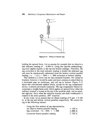
Figure 5-11. Testing for bracket sag.
holding the upward force. Let us assume for example that we observe a
dial indicator reading of - 0.004 in. Using this specific methodology,
sag error applies equally to the top and bottom readings. Therefore, the
sag correction to the total indicator reading is double the indicated sag
and must be algebraically subtracted from the bottom vertical parallel
reading, i.e., - (2) ( - .004) = + .008 correction to bottom reading.
This method is a clever one for face-mounted brackets. For clamp-on
brackets, however, it would be easier and more common to attach them to
a horizontal pipe on sawhorses, and roll top to bottom. Figure 5-12
shows this conventional method which, except for the sag compensator
device, is almost universally employed. The sag compensator feature in-
corporates a weight-beam scale which applies an upward force when the
indicator bracket is located at the top of the machine shaft, and an equal,
but opposite, force when the indicator bracket and shaft combination is
rotated to the down position, 180" removed.
In any event, let us assume that we obtain readings of 0 and + 0.160
in. at the top and bottom vertical parallels respectively. We correct for
sag in the following manner:
Using the first method of sag determination,
we observe bottom parallel reading +.160 in.
Sag correction -2(-.004) = +.008 +.008 in.
Corrected bottom parallel reading +. 168 in.